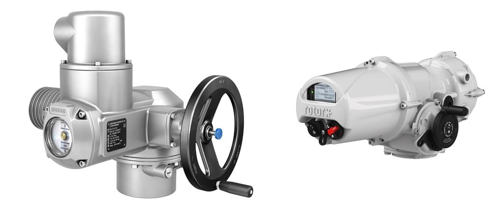
In industrial valve automation and flow control, actuators play an essential role in converting an input signal into physical action. AUMA, a renowned name in the industry, offers a diverse array of electric actuators that cater to various applications. This blog post aims to provide a comprehensive guide on wiring AUMA actuators, emphasizing that each actuator configuration may come with a unique wiring diagram. Whether you’re seeking AUMA actuators or spare parts or simply want to understand the wiring process, this guide should offer valuable insight.
Wiring AUMA actuators involves connecting the actuator to a control system, enabling the transmission of control signals between the two. To get started, let’s break down the necessary steps.

1. Understand the AUMA Wiring Diagram
Before you commence wiring, you must fully understand the wiring diagram associated with your specific AUMA actuator model. A wiring diagram is a comprehensive schematic depicting electrical connections and their specific placement in an actuator. The AUMA wiring diagram, found in the manual that comes with your actuator, is your key resource during the wiring process. It illustrates the wiring for the motor controls, limit switches, and torque switches, among other components.
2. Prepare Your Tools and Materials
To wire an AUMA actuator, you’ll need a few tools and materials, including a set of screwdrivers, wire strippers, wire nuts, and of course, the appropriate electrical wires. Always ensure that you use wires of the correct size and type as dictated by your actuator’s specifications.
Order Original AUMA Actuators and Parts - ProActuator
Do you need AUMA actuators or spare parts?
3. Ensure Safety Precautions
Before proceeding, it’s crucial to follow safety precautions to prevent electrical shocks and equipment damage. Always power down the system and lock out the electrical source before beginning any wiring process. Additionally, always wear safety gear, including insulated gloves and protective eyewear.
4. Wiring the AUMA Actuator
Once you’re prepared, you can begin wiring the actuator. Follow the AUMA wiring diagram closely for each connection. Typically, you’ll start by wiring the motor controls. Next, you’ll connect the wires for the limit switches and the torque switches. Ensure each wire is secure and correctly placed as per the diagram.
5. Testing the Connections
After wiring the actuator, it’s crucial to test the connections. Testing process involves applying power to the actuator and monitoring its operation. If the actuator does not perform as expected, switch off the power, review the wiring, and correct any issues.
It’s important to remember that while these steps provide a general guideline, the wiring diagram of each AUMA actuator can be unique. Therefore, referring to the specific instructions and wiring diagram provided with your AUMA actuator is crucial.
Conclusion
In conclusion, wiring an AUMA actuator is a task that involves understanding the wiring diagram, preparing the necessary tools, adhering to safety measures, connecting the wires as per the diagram, and testing the connections. As you gain experience with different AUMA actuator models, you’ll better understand the nuances involved in their wiring processes.
By adhering to these guidelines and remembering that each actuator may come with its unique configuration, you’ll be better equipped to handle the task of wiring AUMA actuators. Remember, AUMA provides detailed technical information and guidance for each of its products. Make sure to utilize these resources to ensure a successful and safe installation process.


